The schematic editor consists of an overhead component strip (the palette strip), an inspector panel, and a canvas for assembling components.
Figure 1: The schematic editor
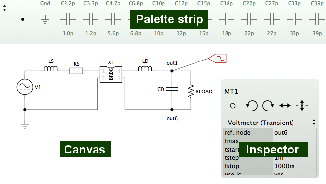
The schematic editor consists of an overhead component strip (the palette strip), an inspector panel, and a canvas for assembling components.
The schematic palette strip is located at the top of the schematic editor and displays a row of schematic elements. It is a convenient component source so that you don't need to deal with the library window for frequently used components. Changes to the contents of the palette strip, however, can only be made in the library window.
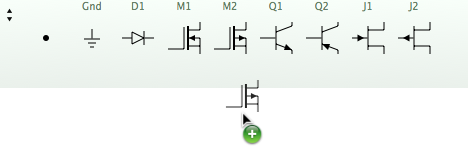
To add a copy of an element to the schematic you simply drag it from the palette to the canvas.
The palette in your library may contain many element groups but the schematic palette strip shows only one group at a time. Select the displayed group with the menu button at the top left.
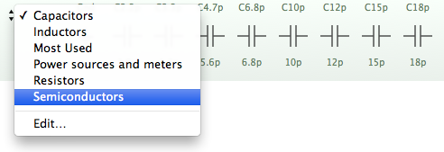
Select "Edit..." to open the library window, where you can make changes.
The palette strip can be hidden (and shown again) with the 'Palette' toolbar button.
The inspector is a panel in the canvas for editing components. With the inspector you can rotate and flip components, change their model and their property values. If a single component is selected, you can also change the component name - as long as the name is not used by another component within the schematic. If multiple components are selected, you can only change the properties that are shared by all components.
The name of the selected component is displayed at the top of the inspector. You can edit the name by clicking and typing. Below are the controls for positioning the label, for rotating, and for flipping (mirroring). Further below is the model chooser where you can select alternative, type-compatible models. Lastly, there is a table of properties and their values. You can start editing a property's value by double-clicking on the field next to the property name.
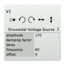
For circuit components, the properties are SPICE properties. Refer to the Ngspice manual for their description.
The inspector can be hidden and shown again by pressing the "Inspector" toolbar button.
The inspector can be attached to any corner of the canvas.
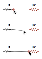
You connect two circuit components by dragging a connection line from the connection point (pin) of the first component to the pin of the second component. Each circuit component has at least one pin. Pins are highlighted in red when the mouse pointer is on top. A pin can accommodate only one connection. Use nodes, which have 4 pins, to join connectors. Disconnecting components is also easy: Simply drag the connector away from one of its connection points and let go.
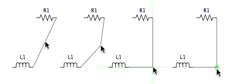
Initially, a connection is a straight line. By dragging points on the linear segments of the connector you can insert joints. To remove a joint you simply drag it back to the (imaginary) line between its neighboring joints (or connection points). Joints are highlighted in green when the mouse pointer is on top.
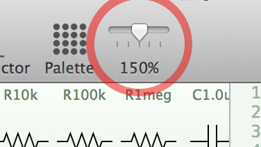
The schematic can be scaled up to twice the standard size. This feature is intended to make working on small, high-resolution displays easier. You can change the zoom factor with the slider in the toolbar (figure 7) or with a pinching gesture on your trackpad.