Nucleo-64: Difference between revisions
No edit summary |
|||
| (4 intermediate revisions by the same user not shown) | |||
| Line 32: | Line 32: | ||
=== Building and Uploading a Program === | === Building and Uploading a Program === | ||
<br /> | <br /> | ||
==== Building with the Mbed Web IDE and uploading with st-flash ==== | ==== Building with the Mbed Web IDE and uploading with ''st-flash'' ==== | ||
The [https://ide.mbed.com/compiler/ Mbed web IDE] can be used to create an executable binary program that is downloaded from the website and uploaded to the GPU. | The [https://ide.mbed.com/compiler/ Mbed web IDE] can be used to create an executable binary program that is downloaded from the website and uploaded to the GPU. | ||
<pre class="terminal"> | <pre class="terminal"> | ||
st-flash write <path to bin file>/myprogram.bin 0x08000000 | st-flash write <path to bin file>/myprogram.bin 0x08000000 | ||
</pre> | </pre> | ||
where 0x8000000 is the address at which the '''flash memory region''' starts on STM32F4 chips. Our program needs to be uploaded into this memory region in order to be executed after a system restart. | where 0x8000000 is the address at which the '''flash memory region''' starts on STM32F4 chips. Our program needs to be uploaded into this memory region in order to be executed after a system restart. Note that the ''st-flash'' tool is part of the [https://github.com/texane/stlink stlink project on GitHub] and not installable from the Ubuntu 18.04 repository. | ||
<br /> | |||
<br /> | |||
==== Building and uploading with Mbed-CLI ==== | |||
Another tool for creating an Mbed project, for building it, and for flashing the generated binary is the tool ''mbed'', which is part of the [[ARM_Mbed#Command_Line_Tools | Mbed Command Line Tools]] and installed the Python package manager PIP. Unfortunately, the flashing function of ''mbed'' requires that the project is completely handled by the ''mbed'' tool. | |||
<br /> | <br /> | ||
<br /> | <br /> | ||
| Line 142: | Line 146: | ||
=== Programming === | === Programming === | ||
For the Nucleo-F411RE, see the [https://www.st.com/resource/en/programming_manual/pm0214-stm32-cortexm4-mcus-and-mpus-programming-manual-stmicroelectronics.pdf STM32 Cortex-M4 MCUs and MPUs Programming Manual] and [https://www.st.com/resource/en/reference_manual/rm0383-stm32f411xce-advanced-armbased-32bit-mcus-stmicroelectronics.pdf STM32F411xC/E Reference Manual] from ST. | |||
<br /> | <br /> | ||
<br /> | <br /> | ||
Latest revision as of 2022-09-18T17:18:00
Introduction
This article is about programming the ARM development board Nucleo-64 STM32F411 by STMicroelectronics. The development environment is Eclipse 4.6.2 (a.k.a. "Neon.2") with the GNU ARM Eclipse plugin running on Ubuntu Linux. If your GNU ARM toolchain is the latest version directly from ARM, then you will have problems debugging in Eclipse because the Eclipse debugger is not able to suspend or terminate the debugging session. You can work around this problem by either debugging manually from the command line or by using Eclipse 4.5.2 (a.k.a. "Mars.2"). It is expected that the problem will be fixed in Neon.3.
I am combining the knowledge I obtained from various sources like the official documentation by ARM Ltd., the tutorial by Patryk Jaworski, where he shows us how to program a Nucleo development board with an STM32F401RE processor by using the GNU ARM cross-compiler and the CMSIS library extracted from the STM32CubeF4 software bundle, the tutorial by Benjamin Vedder, who shows us how to set up the Eclipse debugger for STM32F4 to work with OpenOCD, and a discussion on StackExchange about how to use GDB with OpenOCD
We will be using CMSIS, HAL and assembly code in our program. Fortunately we don't need to extract CMSIS or HAL from the STM32CubeF4 bundle, like Patryk did in his tutorial. The STM32F4xx template project in the GNU ARM Eclipse plugin includes the CMSIS and HAL libraries.
Note that the Nucleo boards do not include a programmable bootloader and ARM Cortex-M usually don't have an integrated bootloader, unlike the ATmega processors used in Arduino boards. The uploaded program therefore gets wiped when power is cut off.
Hardware Overview And Specifications
The Board
 |
|
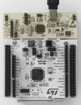
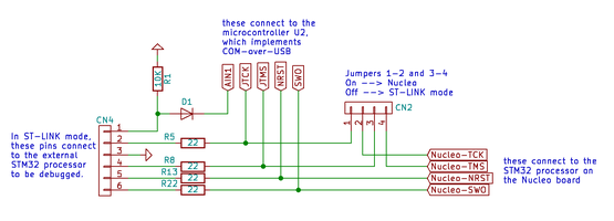
In the picture on the left, the top part of the board is the ST-LINK/V2-1 debugger/programmer for STM32 microcontrollers. It has SWD (serial wire debugging) pins. It can be used to program ARM processors on other boards by connecting the SWD pins (the 6 headers on the left) to the appropriate pins of the other board.
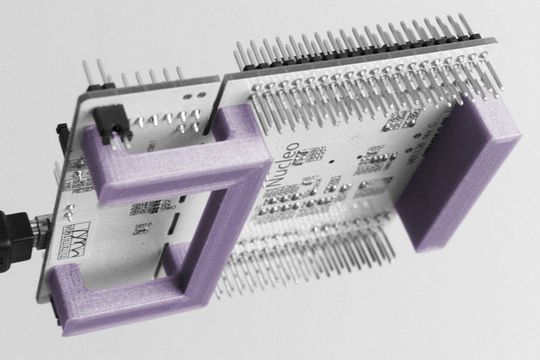
The picture on the right shows the two-piece support structure that I designed to relieve the pins on the bottom side from physical stress. The 3D model of the support is included with the project files.
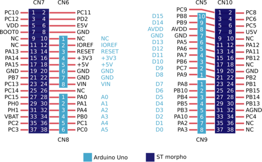
Pin Layout
Building and Uploading a Program
Building with the Mbed Web IDE and uploading with st-flash
The Mbed web IDE can be used to create an executable binary program that is downloaded from the website and uploaded to the GPU.
st-flash write <path to bin file>/myprogram.bin 0x08000000
where 0x8000000 is the address at which the flash memory region starts on STM32F4 chips. Our program needs to be uploaded into this memory region in order to be executed after a system restart. Note that the st-flash tool is part of the stlink project on GitHub and not installable from the Ubuntu 18.04 repository.
Building and uploading with Mbed-CLI
Another tool for creating an Mbed project, for building it, and for flashing the generated binary is the tool mbed, which is part of the Mbed Command Line Tools and installed the Python package manager PIP. Unfortunately, the flashing function of mbed requires that the project is completely handled by the mbed tool.
Building with GNU MCU Eclipse and uploading with OpenOCD
In GNU MCU Eclipse (https://gnu-mcu-eclipse.github.io/downloads/), select "Create a New STM32F4xx C/C++ Project as shown:
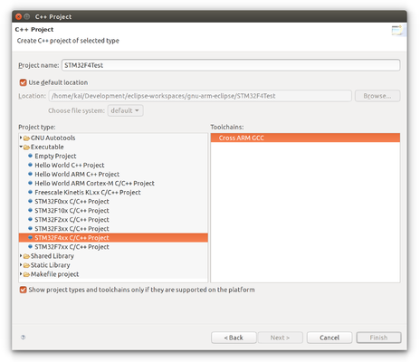
OpenOCD is a command-line tool for flashing binaries onto microcontrollers. Open a terminal window and type
openocd -f /usr/share/openocd/scripts/board/st_nucleo_f4.cfg -c "program <path to build results folder>/STM32F4Test.elf verify reset exit"
where <path to build results folder> needs to be replaced by the path to the build results folder (= <project folder>/Debug for debug builds). OpenOCD will use the specified configuration file for STM32F4 Nucleo boards and execute the given commands to transfer the ARM program corresponding to STM32F4Test.elf, verify the transferred binary, reset the microprocessor so that the program starts from the beginning, and exit execution after closing its connection to the board. The program will continue running on the board after OpenOCD exits.
The commands executed by OpenOCD can also be issued from a second terminal session while in the first terminal session OpenOCD runs in server mode via
cd <project folder>
openocd -f /usr/share/openocd/scripts/board/st_nucleo_f4.cfg
and waits for the telnet connection on port 4444. In the second terminal you just type
cd <project folder>
telnet localhost 4444
to connect to OpenOCD. Now issue the commands
> reset halt
> arm semihosting enable
> program Debug/STM32F4Test.elf verify reset
or, alternatively,
> reset halt
> arm semihosting enable
> flash write_image erase Debug/STM32F4Test.hex
> reset
to load and run the generated program. Note that the working directories are the same in both terminals so that relative file paths can be used. Also note that we enabled ARM semihosting, which binds the I/O of the program that runs on the ARM processor to the I/O of the terminal that we are running OpenOCD from. Otherwise we would not be seeing the debug (trace) messages in the first terminal.
To disconnect the telnet client from the OpenOCD server, type
> exit
The OpenOCD server and the ARM program will keep running. You can connect again with a new telnet session. To stop the server (and the program), press Ctrl+C in the first terminal.
Debugging With OpenOCD
First of all, you should make sure GDB for ARM is installed. Either install from the default repository
sudo apt install gdb-arm-none-eabi
or download the latest version directly from ARM.
Command-Line Debugging With GDB/OpenOCD
Open two terminal sessions. In the first terminal start OpenOCD as server:
openocd -f /usr/share/openocd/scripts/board/st_nucleo_f4.cfg
Note that your working directory does not matter when starting OpenOCD. In the second terminal, start GDB, connect to the OpenOCD server on port 3333, load the program and run it:
cd <project folder>
arm-none-eabi-gdb Debug/STM32F4Test.elf
> target remote localhost:3333
> monitor arm semihosting enable
> monitor reset halt
> load Debug/STM32F4Test.elf
> continue
Here we use the GDB command monitor to send messages (usually commands) to the remote target. The line "monitor arm semihosting enable" is needed for continue to work. After continue, use the GDB commands to pause execution (Ctrl+C), set breakpoints, inspect stack variables, and so on.
Setting Up The Eclipse Debugger
Read the instructions in the GNU ARM Eclipse documentation. In our case, the Config options string that needs to be entered is -f /usr/share/openocd/scripts/board/st_nucleo_f4.cfg.
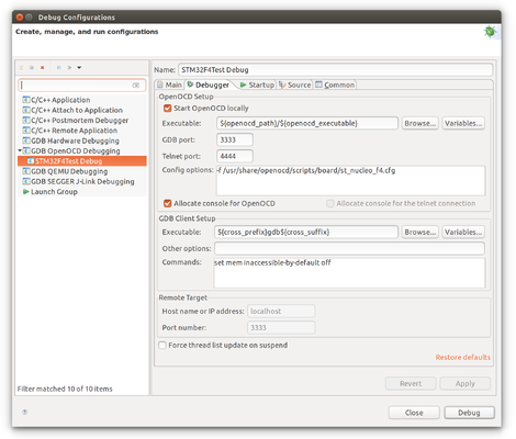
DFU mode
Pin #7 on the outer left male header row CN7 is the BOOT0 pin. Pin #5, right next to it, is VDD. So, in order to enable writing to the boot memory via USB we simply cap these two pins with a jumper. The bootloader thus switches to DFU mode after resetting the STM32. USB data wires D+ and D- need to be connected to pins PA12 and PA11, respectively. PA11 and PA12 are located on the male header row CN10 on the right side.
DFU bootloader configuration for STM32F411 according to ST application note AN2606
| Feature/Peripheral | State | Comment |
|---|---|---|
| USB | Enabled | USB OTG FS configured in Forced Device mode |
| USB_DM pin | Input/Output | connects to STM32 pin PA11 |
| USB_DP pin | Input/Output | connects to STM32 pin PA12 |
| TIM11 | Enabled | This timer is used to determine the value of the HSE. Once the HSE frequency is determined, the system clock is configured to 60 MHz using PLL and HSE. |
The system clock is derived from the embedded internal high-speed RC for USARTx, I2Cx and SPIx bootloaders. This internal clock is also used for DFU (USB FS Device) but only for the selection phase. An external clock multiple of 1 MHz (between 4 and 26 MHz) is required for DFU bootloader execution after the selection phase.
Programming
For the Nucleo-F411RE, see the STM32 Cortex-M4 MCUs and MPUs Programming Manual and STM32F411xC/E Reference Manual from ST.
Global Variables
| HSE | external high speed clock, usually more accurate than the internal clock HSI |
| HSI | internal high speed clock |

