HC-SR04: Difference between revisions
Adds oscilloscope screenshot. |
|||
| Line 55: | Line 55: | ||
* Calculate the distance from the time that the ultrasonic waves spent travelling in air (distance = time * velocity / 2, where the velocity of ultrasonic waves in air is 340 m/s). | * Calculate the distance from the time that the ultrasonic waves spent travelling in air (distance = time * velocity / 2, where the velocity of ultrasonic waves in air is 340 m/s). | ||
</p> | </p> | ||
[[File: | [[File:Sensor_HC-SR04_signals.png | x400px ]] | ||
=== Limitations === | === Limitations === | ||
Revision as of 2025-05-02T07:21:01
The information here about the HC-SR04 ultrasonic distance sensor is based on vendor datasheets and various online sources, including a ModMyPi article for Raspberry Pi and the Elecfreaks user guide for integration into Arduino.
Sensor Properties
| Operating Voltage | 5 V DC |
| Operating Current | 15 mA |
| Operating Frequency | 40 kHz |
| Nearest Range | 3 cm |
| Farthest Range | 4 m |
| Beam Angle | 15 degrees |
| Input Trigger Signal | 10 μs TTL pulse (low: 0-0.8 V, high: 2 V to VCC, where VCC = 5 V ±10%) |
| Output Echo Signal | Output TTL level signal, proportional to range |
Wiring and Voltage Levels
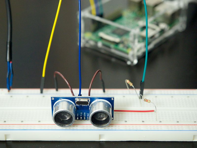
The sensor module has four pins:
- Gnd for Ground,
- Echo for the ultrasonic echo output signal,
- Trig for the ultrasonic burst trigger signal input, and
- Vcc for the 5 V supply voltage.
The sensor circuit is designed for TTL-level signals (0 V for LOW and 5 V for HIGH). The GPIO pins of most microcontrollers and single-board-computers are designed for 3.3 V, however. Sending a 5 V signal into an unprotected 3.3 V GPIO pin of a Raspberry Pi, for example, could damage the pin. A simple voltage divider circuit, consisting of two resistors, can be used to lower the sensor output voltage to 3.3 V.
Operation
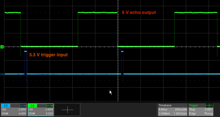
The controller starts the range measurement by raising pin TRIG to 5 V for at least 10 μs and thereby triggering eight 40 kHz ultrasonic pulses (beyond the 20 kHz high frequency limit of human hearing). The pulse waves bounce off any nearby objects and some are reflected back to the sensor. The sensor detects these reflected waves and raises the ECHO pin to 5 V for a duration proportional to the distance of the objects that the waves are reflected from.
A single range measurement is therefore performed like this:
- Initialize by setting the TRIG and ECHO pins to LOW.
- Raise the TRIG pin to HIGH for at least 10 μs.
- Wait for a rising edge on the ECHO pin, start a timer when detected.
- Wait for the falling edge on the ECHO pin, stop the timer when detected.
- Calculate the distance from the time that the ultrasonic waves spent travelling in air (distance = time * velocity / 2, where the velocity of ultrasonic waves in air is 340 m/s).
Limitations
The ultrasonic sensor is not able to measure distances to objects with highly diffuse surfaces or surfaces that are angled so that most incoming waves are reflected away from the sensor.
Programming Examples
Raspberry Pi / Python
The code below assumes that the output to the sensor's TRIG pin is connected to GPIO #23 and the input from the sensor's ECHO pin is connected to GPIO #24.
import RPi.GPIO as GPIO
import time
GPIO.setmode(GPIO.BCM)

TRIG = 23
ECHO = 24

print "Distance Measurement In Progress"

GPIO.setup(TRIG,GPIO.OUT)
GPIO.setup(ECHO,GPIO.IN)

GPIO.output(TRIG, False)
print "Waiting For Sensor To Settle"
time.sleep(0.25)

GPIO.output(TRIG, True)
time.sleep(0.00001)
GPIO.output(TRIG, False)

while GPIO.input(ECHO)==0:
  pulse_start = time.time()

while GPIO.input(ECHO)==1:
  pulse_end = time.time()

pulse_duration = pulse_end - pulse_start

distance = pulse_duration * 17150
distance = round(distance, 2)
print "Distance:",distance,"cm"

GPIO.cleanup()


