LT0
Introduction
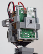
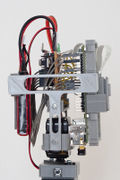
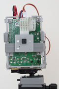
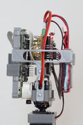
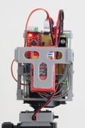
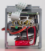
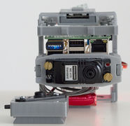
LT0 ("el tee zero") is a robot equipped with a camera and capable of turning around the vertical axis to keep the camera pointing at a tracked moving object. LT0 may not be a robot in the popular sense but nevertheless it's a computerized device that controls a mechanical actuator to autonomously fulfill a task. LT0 is a cheap test device for the software that will power the submersible RF0. LT0 has a servo motor that can rotate the body, including the Core Raspi module with its front-facing camera. The photos below show the prototypical LT0 unit I built.
The design of LT0 follows the concept of splitting the hardware into two parts: (1) a robot body that is specific to the application and whose actuators and sensors are controlled by a Robot State Agent (RSA), (2) a reusable Core with a Robot Task Controller (RTC) that runs the higher-level control software and communicates with the RSA. The RTC unit in LT0 is implemented with a Raspberry Pi, and the RSA unit is an Arduino microcontroller with sensors, actuators, and power control circuitry. In LT0, the RSA is actually redundant. The Raspberry Pi is capable of controlling the servo motor and reading sensor data while simultaneously processing the images from the camera. However, LT0 is a test platform for more complex designs (LT1 and RF1) in which the split between RTC and RSA is more meaningful because the RTC could be overwhelmed by the processing sensor data and controlling actuators in real time.
The project files are available on GitHub.
Parts
- Core Module with Raspberry Pi 2 (or 3 or 4) and Pi NoIR camera v1
- RSA circuit board (see Electrical Design below) with
- Wattuino Pro Mini board (3.3 V, 8 MHz)
- microcontroller: ATmega328 with 30 KB Flash, 2 KB RAM
- RECOM R-785.0-1.0 switching voltage regulator (5 V, 1 A output)
- DS18B20 temperature sensor
- MPU-9250 gyro/accelerometer/magnetometer (a.k.a. IMU)
- FET and BJT transistors for power control
- resistors
- Wattuino Pro Mini board (3.3 V, 8 MHz)
- BMS-410C servo motor to rotate the Core around its long axis
- 7.4 V LiPo battery
- Arca-Swiss mount with push button for turning the power to the Core on or off
Mechanical Design
|
|
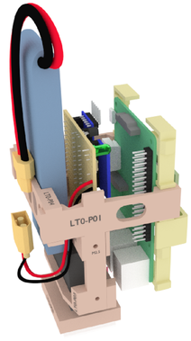
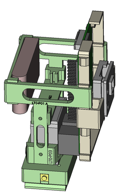
I first designed the structure using Blender (left image). Later I switched to FreeCAD as my 3D modeling tool (right image).
The servo motor is able to rotate the upper body of the device so that the camera of the Core module can track a slow moving object.
Electrical Design
Design tool: KiCad
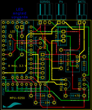
The PCB layout is realized on a 50x50 mm circuit board with header pins for connecting to the GPIO pins of the Raspberry Pi, to the servo motor, to the battery, and to the push button. The three layers of connecting tracks in the design (red, yellow, green) do not apply to the hand-soldered prototype seen in the photos.
|
|
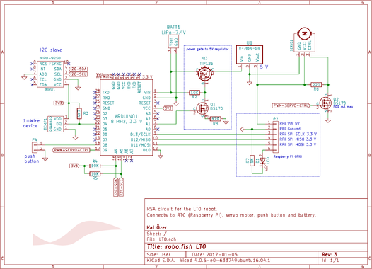
The BS170 and TIP125 switching transistors are used in conjunction to control the power to the Raspberry Pi. The Arduino is programmed so that the power gate is toggled when the push button is pressed. When the BS170 is switched on, the value of the resistor R8 affects the current that flows to the base of the TIP125, and, therefore, the current that flows from the battery to the 5V regulator U1 (and the RPi). I tried a couple of values for R8 to find one that keeps the idle current low yet does not restrict the current flow to the regulator much. 470 ohms for R8 seems to be the sweet spot.
| R8 | IR8 |
|---|---|
| 47 Ω | 22 mA |
| 470 Ω | 3.1 mA |
| 1 kΩ | 1.4 mA |
| 1.5 kΩ | 1.0 mA |
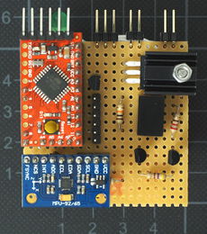
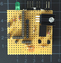
In the prototype, the expensive Arduino and IMU boards are not soldered on the RSA directly. Pin sockets are soldered on the board instead, allowing the Arduino and IMU to be removed and reused in other circuits.
|
|
Software
The software is available on GitHub, along with the hardware design documents for LT0.
RTC
The LT0 RTC will be equipped with a pre-trained FishNet B neural network to detect humans in upright standing posture. For this purpose the RTC will be capable to connect with an external deep learning workstation and stream its camera captures.
The RTC software is written in C++ for running on a Raspberry Pi. The following libraries are used:
The Raspberry Pi camera needs to be enabled for the software to work. Use the command-line tool raspi-config to enable or disable the camera.
Also make sure the libraries can be found by the library loader during runtime. Assuming they have been installed under /usr/local/ (the default location for make install), the file /etc/ld.so.conf should include the line
include /usr/local/lib
RSA
The RSA software runs on an ATmega328 microcontroller (on a board that is compatible to Arduino Pro Mini).
RTC⇄RSA
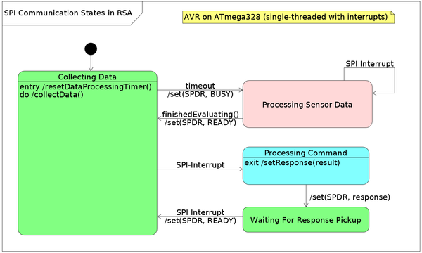
RTC and RSA communicate via SPI according to this octet-sized protocol:
| RTC commands | RSA responses | ||||
|---|---|---|---|---|---|
| symbol | code | parameter (5 bits) | symbol | code | parameter (6 bits) |
| GET_GYRO | 0x20 | - | BUSY | 0x00 | - |
| GET_TEMP | 0x40 | external (0) / CPU (1) | READY | 0x40 | - |
| SET_SERVO | 0x60 | angle | ACK | 0x80 | command code |
| GET_COMPASS | 0x80 | - | RSP | 0xC0 | value |
| SLEEP | 0xA0 | duration | |||
| RESPOND | 0xC0 | - | |||
Commands (from the RTC to the RSA) are 8 bits long. The most significant 3 bits are the command type. The remaining 5 bits are for the command parameter, if any. Responses from the RSA to the RTC are also 8 bits long, where the most significant 2 bits denote the response type. The remaining 6 bits are used to pass numeric values. Floating point values are passed as quantized values within a predefined range. Temperature values are quantized as steps of 1° C, in the range from 15° C to 78° C.
If the RSA responds with BUSY, the RTC will try again after a short delay. The RSA will be busy while it processes the collected sensor data (to reduce noise, for example).
Manufacturing
I made the structural parts with a 3D printer and soldered the components on the circuit board by hand 😩
Roadmap
- Structural design ✓
- Electrical design ✓
- Manufacturing ✓
- Basic functional software
- Testing and debugging

